
Inside a CRT
The Physics Of An Old Television

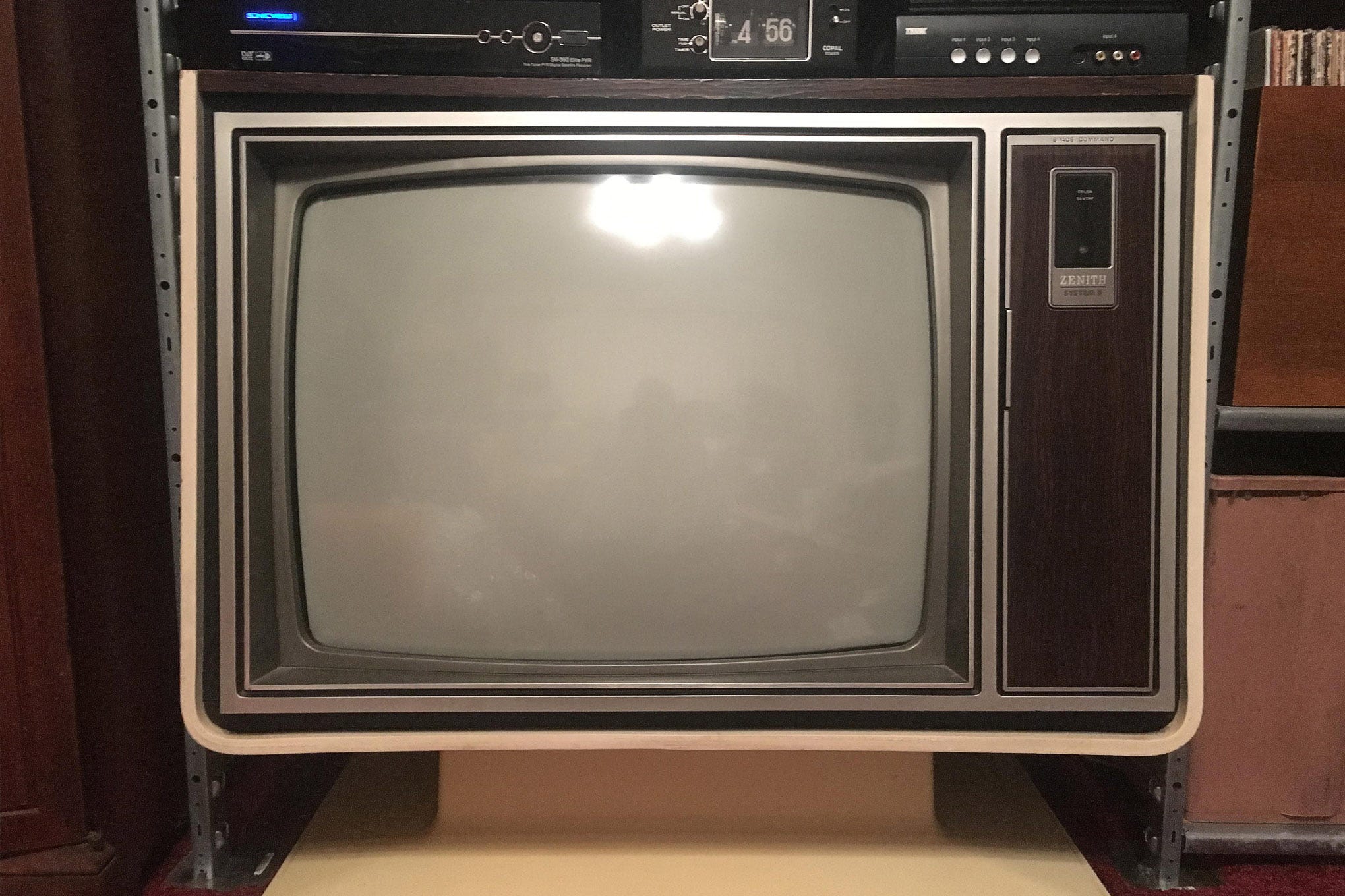
A couple of weeks ago, while mindlessly scrolling, I came across a video of someone reviving an old CRT television. Watching that thick glass screen flicker back to life felt strangely satisfying.
It reminded me that a few years ago, I had been given two old CRT TVs to open up and tinker with. At the time, I treated them like oversized relics; heavy, outdated, obsolete.
But seeing that video made me curious again. Before prying one open, I wanted to actually understand what was happening inside that massive glass box.
A CRT tv at its core consists of an electron gun, deflection coils, accelerator anode and focusing anode along with the phosphor screen.
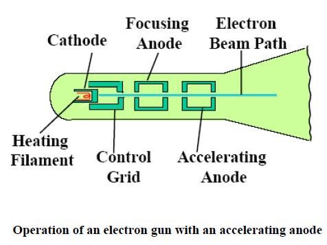
The electron gun- filament and cathode
The electron gun consists of a filament, which is a thin tungsten wire, coiled up. This wire it supplied a low voltage, high amperage current that causes it to heat up to around 2500K. This also explains why old CRTs took so long to start up. When heated, it warms the cathode, usually a nickel cylinder coated with alkaline earth metal oxides, causing electrons to be released from it; this phenomenon is known as thermionic emission. This is contained in a glass container under vacuum. The reason we need a vacuum inside is to prevent the beam from scattering, allowing it be more concentrated and narrow.
Between the screen and the electron gun, there is a large potential difference (from 15,000 to 30,000 volts). The electron gun acts as the cathode, and the screen as the anode; this causes the electrons to shoot a concentrated beam of electrons towards the screen.
The grid, accelerating anode and focusing anode
After the electrons are produced, they pass through the grid on the way to the screen. The grid has a slight negative charge, which repels electrons. This negative charge is adjusted to regulate the flow of electrons out of the gun. This is required to adjust the screen brightness. As more electrons collide with the screen, a brighter image is shown.
When an electron is launched from the cathode, it must be accelerated for it to gain enough kinetic energy to excite the phosphor, heating it up and allowing the thermionic emission. This is done by adding another anode between the screen and the electron gun through which the electrons travel.
After dispersing out of the cathode, passing through the grid and accelerating anode, the electrons are dispersed and are travelling in a spread-out pattern. To produce a clear image, they must be thin and controlled. For this, a focusing anode is used. Simply put, it uses a lower positive potential than the accelerating anode, creating an electric field configuration that acts like a lens, narrowing the electron beam.
So far, we know how the actual electrons get launched towards the screen:
If we left it at this, we would just get a dot at the centre of the screen showing where the electrons are landing. How do we control where the electrons go, and how does it actually produce any image?
This is where Deflector coils come into play.
The deflector coils are electromagnets that adjust their magnetic field to change the direction of the electron beam.
Two deflector coils are used:
Vertical deflection coils
Horizontal deflection coils
To understand further, the best thing to do is watch this GIF

(Over here, it shows the actual magnets moving, but in reality its only the strength thats changed)
Here you can see the adjustment of the Vertical deflection coils changes the movement of the electrons vertically, along with the Horizontal deflection coils changing the electron beams direction horizontally. If you have understood this, you will understand that this way of depicting an image requires each pixel to be shown individually at once. To make the image actually visible, the vertical coils are regulated at a frequency of 50 to 60 H,z and the horizontal coils work at several thousands of times per second. This was required for the display to have a refresh rate of 60Hz.
All this makes so much sense when we look at it from above, after all the science and maths click together to create the final product, but just imagine how complicated it would have been to come up with this from scratch. This is just for a Black and white display, it’s hard to think how much more complicated a colour display would be!
this da real CRT explanation!!